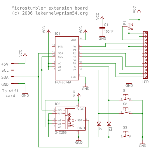
Building the external board
You'll need the following parts :R1 - contrast control, any potentiometer between 4.7k and 22k should be fine.
C1 - decoupling capacitor, around 100nF.
D1, D2 - general purpose diodes, 1N4148 is an example of suitable diode.
S1, S2, S3 - any pushbutton that looks good to you.
IC1 - PCF8574A I2C GPIO expander. Strangely enough, the PCF8574A seems cheaper than the PCF8574 although they differ only by they slave address. If you want to use a PCF8574, it will work but you'll have to change the I2C address in the ISL38xx firmware.
IC2 - 24C256 I2C serial EEPROM. Used to store the ISL38xx firmware.
LCD - 1x16 characters LCD module based on some HD44780 clone. If you choose to scavenge it from consumer electronics, most modules that have a 14-pin connector in the top-left corner of the PCB and look like the one on this snapshot are of the suitable type. Anyway, check the datasheets if you can find them.
Build the circuit according to these schematics. No PCB has been made, use Veroboard (contributions welcome...).
Beware ! If you modify the circuit, keep in mind that the I2C bus is 3.3V altough the rest of the Microstumbler board is 5V. In particular, don't connect pull-ups to 5V to the I2C signals. You can cause irreversible damage to your wifi card.
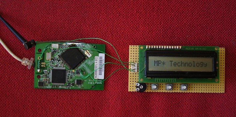
Connecting the board to your wifi card
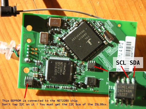
First, tap the 5V power supply on the USB connector. On the USB plug that goes to the computer, the power supply pins are those at the extremities of the connector. Use an ohmmeter to figure out on which solder pads these pins are connected to on the PCB of the wifi card, solder wires to them, then plug the card and use a voltmeter to find out the polarity. You can easily fry parts if you power them up the wrong way, especially the LCD module. Connect this power supply to the Microstumbler board, on the pins labeled "+5V" and "GND".Then, to connect the I2C bus, you need to find where the serial EEPROM of the wifi card is. It is typically a 8-pin SMD package labelled 24Cxx. On the 24Cxx EEPROMs, the signals SDA and SCL are respectively on pins 5 and 6 ; if your wifi card uses a different EEPROM, check its datasheet. Use very thin wire to tap these signals, then glue the wires to the EEPROM package using cyanoacrylate to avoid damaging the EEPROM pins and solder pads by pulling on the wires. Double check you did not make any short circuit, the SMD package of the EEPROM is quite small.
Here is a snapshot of a Siemens Gigaset USB Adapter 54 version 1 :