FreeMAC history
The primer
The project started in August 2005, rather motivated by curiosity than by the goal of writing a fully-fledged, wireless-enabled firmware. I knew that the firmware was software that was run by an ARM CPU embedded in the ISL38xx chip, and I just wanted to know how simple things were done in the device, such as triggering interrupts on the PCI bus or controlling the LED.So I installed an ARM toolchain according to the instructions at http://www.gnuarm.com/, assembled my first program, containing just a "NOP" instruction and tinkered with objcopy so that it produced something resembling an ISL38xx firmware, ie. bare ARM code (well, I assumed it was only ARM code...) ; a file containing "00 00 A0 E1" (the opcode for NOP) in that particular case.
Then, I had to write a device driver capable of loading the hacked firmware and then performing very low-level communication with the device. I thought of polling the two so-called "PCI general purpose communication registers" of the ISL38xx : I guessed those registers would be simply memory-mapped in the ARM. So I took my p54u driver, renamed it to "islldr" (ISL38xx LoaDeR) removed all networking-related code and added a timer which periodically read the registers, printing their values to the kernel log.
Finding the ARM addresses where the general purpose communication registers were was the real problem. Disassembling the official firmware shown references to 0xc000xxxx and 0xa000xxxx memory areas, so I wrote an ARM assembly program which wrote each register in those banks with its address, loaded it with islldr into my Siemens Gigaset (USB version 1 device), and that did not work. The register remained at zero, as they are after a device power-up. So many things could have gone wrong : maybe the ARM just did not run my code, maybe the PCI bus needed to be initialized, maybe the guess that the general purpose communication registers were memory-mapped was wrong...
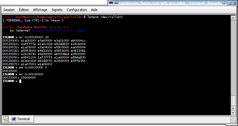
Fortunately, looking at the firmware upload process, I had another idea. Indeed, with version 1 USB devices, after each 512-byte firmware block is sent into the NET2280 buffer, a value in the PCI I/O space of the ISL38xx is loaded with 0xc0000f00 - a value really looking like being in the ARM hardware address space - then PCI address space after 0x1000 is manipulated. After looking at other source codes (FullMAC and XH8196 drivers), I understood how this worked. This is the "memory window" mechanism, allowing to map an arbitrary portion of the ARM address space to the PCI address space. So to find out the general purpose communication registers addresses, I wrote a magic number to them from the PCI address space (they are at 0x20 and 0x24), and then used the memory window to scan the ARM memory for the magic. The program found back the magic numbers at 0xc0000920 and 0xc0000924 :)
The next step was to access the registers from the ARM. I wrote an assembly program which wrote 0xdeadbeef to 0xc0000920, loaded it in my wireless device, and islldr told me the value of the first general purpose communication register had changed to 0xdeadbeef. Hurray !!!!
I quickly found out how to send PCI interrupts to the host - I knew that was related to the register 0x00 in the PCI address space (the driver reads this register after an interrupt to identify it), so I guessed I had to write the interrupt ID number I wanted to trigger to 0xc0000900. It worked immediately !
The next day (yeah, you see, it was about 3 a.m. when I got my first PCI interrupt from my hacky firmware ;-), I implemented a very basic command-line in the firmware, resembling UARTPCI, that used polling on the ARM side (I didn't know how to send interrupts from the host to the ARM yet), interrupts on the host side and the two general purpose communication registers to transfer the ASCII data. ISLMON (ISL38xx MONitor) was born.
Let's write a GPL firmware...
Then, I improved ISLMON bootstrapping - well, ISLMON was working, but with so many things unconfigured: vector table, stack (every function call was probably corrupting code or other data, it was quite a miracle that it worked...)... I also understood how the code and data TCM (Tightly Coupled Memory - see ARM docs) were used on this chip, and how the official firmware, while running from the "normal" memory (the one starting at 0x00020000) unpacked itself into the TCM, then using the "normal" memory for other purposes.Jean Baptiste used the Virtera ARM simulator to get an unpacked official firmware to disassemble. Later, the decompression algorithm was found out by Denis and him, so that we can get rid of heavy ARM simulation using proprietary software (we tried free emulators, but none worked properly with the ARM9).
Disassembling the 2.4.3 USB firmware and looking at the firmware upload process of the USB version 1 devices (the registers acceeded through the memory window are registers that control the DMA engine ; they are used to write the firmware to the device's memory efficiently), he found out how to perform DMA transfers to and from the PCI bus.
With the help of Jean Baptiste, I found out how what I called the "event subsystem" worked. This system gathers all interrupt sources from the chip and allows the firmware to precisely select what event should be ignored, trigger an IRQ in the ARM or a FIQ (Fast Interrupt Query, a high-priority interrupt - see ARM docs). I was then able to rewrite my command-line interface "cleanly", ie. using asynchronous interrupt-driven transfers and not busy waiting on hardware registers.
At this time, ISLMON was renamed to FreeMAC (to make some fun of Conexant/Intersil's "FullMAC" and "SoftMAC"): as we found reverse engineering very interesting, we decided to launch the project of writing a fully fledged firmware.
However, the big thing was missing : we completely lacked access to the radio. To reverse engineer it, I imagined a technique which consisted in emulating the firmware on a computer, but mapping unknown hardware registers and interrupts to the real hardware and logging what happened to them. To acheive this, the memory window was used and a special small firmware was uploaded into the device, which alerted the computer every time an interrupt was happening inside the device.
I implemented this using ARMulator from the GDB source, and it began to work. Emulating the 0.8.0 (FullMAC PCI !) firmware and mapping hardware registers to my Siemens Gigaset (SoftMAC USB !) I found out how to turn on the LED of my device, since this firmware was turning it on at startup.
But I gave up this technique. First, many ARM9 features are missing in ARMulator ; I implemented some but that's really a pain. Then, the radio timings would not be respected and in the PrismII I read that some are really critical. Finally, many features were using in-chip DMA, so the technique would also require synchronizing the emulator's memory with the device's - complicated and consuming USB/PCI bandwidth heavily. The technique did not have so many advantages over dead listing analysis, after all.
Looking closely at the two register writes needed to turn on the LED and experimenting with them, I guessed the chip had GPIO (General Purpose Input and Output) pins, and how to configure them. Analysing the disassembled firmware, Jean Baptiste found out the I2C EEPROM of the device was also connected directly to the GPIO pins, and to which ones. Later, I implemented in FreeMAC a software I2C bus protocol on these two GPIO pins, and was able to read the EEPROM.
Denis and I also figured out some information about the hardware cryptography accelerator of the chip, using in-chip DMA to encrypt any portion of the memory with no intervention of the ARM. We still lack many details (key and algorithm setup), but this is not a priority, we can do software encryption in the host for now.
Denis found out how to set up data transfers to and from the radio, but we don't know how to trigger them yet nor how to set up frequency, TX power, rate, modulation and preamble. We have some hints, however :)
The 3887's USB interface was another problem ; but thanks to Edis who rewrote the GW3887 ROM in C, we eventually managed to make it work.
If you want to help us, you're welcome :)